
Variable Frequecy Drives
Delta CP2000 VFD – Photon and Electron
This guide will show you how to connect the Polar Monitoring Gateway to the Delta Photon and Electron VSDs, otherwise known as the Solar and Irrigation drives. It will also take you through the setup and provide you with the parameters required on these specific versions of the CP2000 to ensure communications to the Polar Gateway.
Steps to follow:
- Connect power to the Gateway.
- Connect RS-485.
- Final checks.
- Power on the system.
- Configure the CP2000 Serial Parameters.
Delta CP2000 Connection Setup
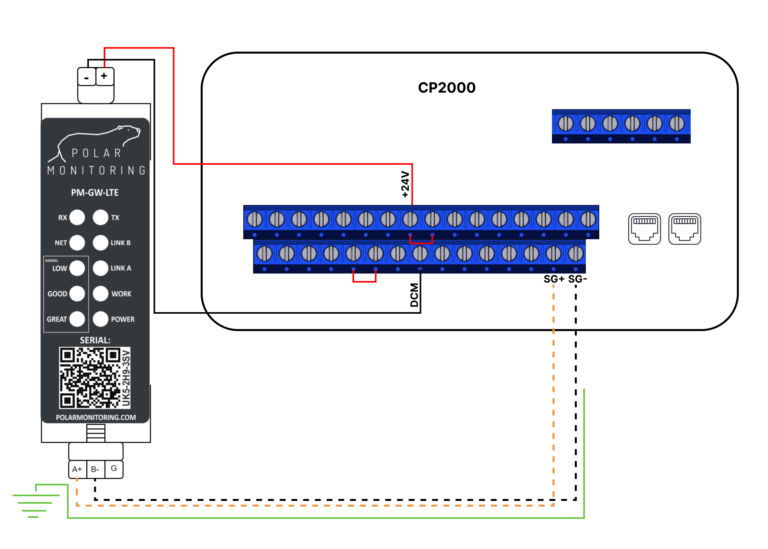
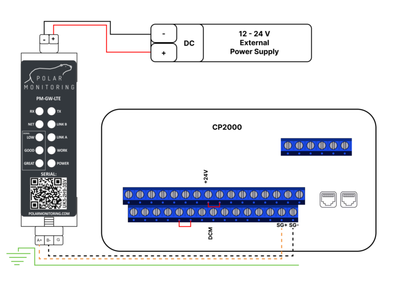
1. Connect power to the Gateway.
A. Powered from an External Power Supply

Wire the Polar Gateway to a 12-24 V DC power supply. Connect the positive wire to the positive terminal and the negative wire to the negative terminal.
B. Powering the Gateway from the VSD.
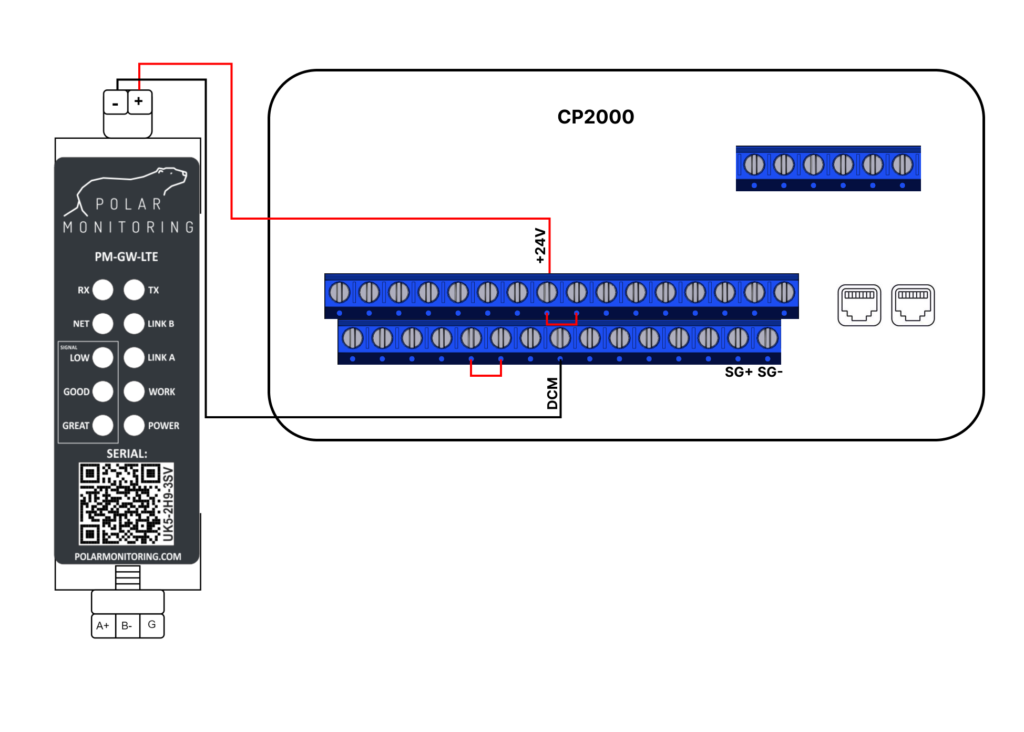
Wire the Polar Gateway directly to the VSD for power. Connect the positive wire to the +24V terminal and the negative terminal to the DCM terminal.
2. Connect RS-485.
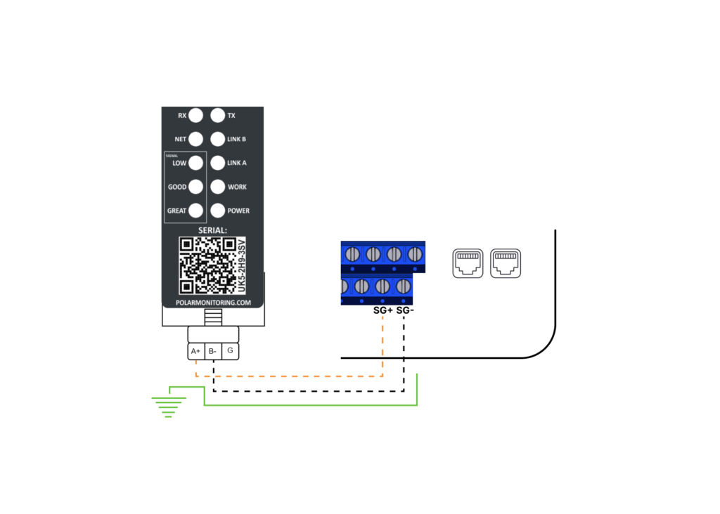
Wire the RS-485 cable to allow communication with the Polar Gateway. Connect A+ => SG+ and the B- => SG-. What is RS-485?
3. Final checks
- Make sure the wiring is secure – no short circuits.
- Ensure that all connections are secure on the device and the gateway.
- Re-check the RS-485 twisted pair cable is correctly wired.
- Check that the A and B are correctly wired to the device.
4. Power on the system
Now you are ready to go, you can now switch on the Polar Gateway and the Delta CP2000.
5. Configure Delta CP2000 Serial Parameters
Note: It is critical to change the default settings to reflect the table below.
Serial Communication Setup
| Name | Description | Parameter | Default | Required |
| Communication Address | PLC Station Address | 09-35 | 2 | 2 |
| Baud Rate | Communication Speed | 09-01 | 9.6 | 9.6 |
| COM1 Protocol | Communication protocol and Data Format | 09-04 | 1=7, N, 2 (ASCII) | 12=8, N, 1 (RTU) |
Remote Control Setup
Modbus registers can be edited and monitored remotely, but to enable remote control of the variable speed drive the below registers must be set accordingly.
| Name | Description | Parameter | Default | Required |
| Operation Command Source (AUTO, REMOTE) | Determines the operation frequency source in the “AUTO, REMOTE” mode. | 00-21 | 0 | 2 |
| Master Frequency Command Source (AUTO, REMOTE) | Determines the master frequncy source in the “AUTO, REMOTE” mode. | 00-21 | 0 | 2 |
| LOCAL/REMOTE selection | Determines the mode selection. | 00-29 | 0 | 4 |
You may now sign in to the Polar Portal to monitor the device remotely, the button on the right will take you through a setup process.